Showing posts with label Dry riser. Show all posts

Monday, August 23, 2010

Engine installation almost completed.....


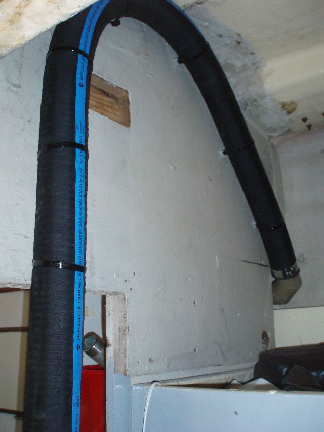
Dry riser solution, finally.


Water lift.


Shooting aft from the engine room door.


Exhaust hose.


Anti syphon.


Transmission access, not too horrible.


Hose run down port side of hull, to exit at stern. I will secure it in place to give a gentle downward slope.

Monday, June 14, 2010

Doctors differ and patients die..........

Well not as dramatic, but lots of conflicting advice on the dry riser. The previous post on the subject quoted the ABYC standard which stated; "No galvanized steel, no brass, no bronze". I have sourced Carbon Steel and this is on standby. Two mechanics, that I have huge respect for, individually suggest galvanized steel and silicon bronze respectively. But I have a cunning plan. I have purchased a second exhaust elbow (hip hip for ebay) and will carry a spare setup.


I am having both elbows cut as indicated above and a 2" threaded galvanized piece welded in place. I can then thread on an 90deg elbow, 18" of pipe, a second 90deg elbow and then the water injecting part of the above. Initially I will use galvanized pipe (cheap and available) but carry the silicon bronze AND the carbon steel as a spare. After a few hundred hours running I will take the riser apart and work from there.

Sunday, April 25, 2010

Correct material for Dry Riser for engine exhaust...

Table 1 in the same Article specifies allowable materials for exhaust systems. The dry exhaust list specifies aluminized steel, carbon steel, nickel-iron chrome and stainless steel. No galvanized steel, no brass, no bronze.

Reference: http://www.ntsb.gov/Dockets/Marine/D...012/234864.pdf

This is the idealised recommendation from the Perkins Sabre installation manual;

"The general arrangement (A) shows that the dry part of the system extends to a safe height above the water line, using an elbow (A1), a stainless steel bellows (A2), a riser pipe to give the required height (A3), and a further elbow (A4), which is supported from the deck head by a flexible hanger, which supports the weight of the system but permits movement side to side and fore and aft."

"The minimum diameter of the dry part of the system should be 40mm (1.6”) for the M65 and the wet part of the system should be not less than 63.5mm (2. 1/2”).

We will see how close we can get. ANY and ALL recommendations and advice graciously accepted.

Wednesday, April 21, 2010

Engine exhaust.......

Jim, the guru is trapped in Urop by the evil Icelandic dust so I have time to try and plan the engine exhaust system. From the measurements, I will need a 20"dry insulated riser, with the cooling water injected on the down side.

These are the measurements on TIH.


These are the recommendations from the Vernalift website;


(diagram courtesy of Centek Ind.)

Obviously I have to watch out for excessive back pressure. Any advice welcome.


Thursday, December 18, 2008

Slowly, slowly catchee monkey.....

Before:


After:


Small improvements in the Engine room. Paint is Interlux Bilge coat, which now comes in dark gray and white. This color is achieved by mixing both.

I painted the wooden panels with "Silent Running SR1000" paint which I have discussed in a previous post.

I know that once I start filling the Engine Room with the usual junk I will not have this much access ever again. Next step is the bulkhead insulation.