Showing posts with label Engine. Show all posts

Friday, October 1, 2010

Cutting holes........

The previous engine control panel was located on the binnacle. I won't have that option. I have spent some time trying to decide where to put the new one. Many boats have the panel low down in the cockpit well. I don't like that for a few reasons (water damage and having to bend down to read etc.).


Nice to cut in and find good adhesion between the outer layer and the balsa core.


Bigger gap between the cabin top and the liner than I expected. Good for running lighting electrical cables etc.


Good fiberglass


Red background is temporary, will eventually be black starboard.

Wednesday, September 22, 2010

Getting things bolted down and boxes up....


Soemtimes you just have to finish a project and put the panel back on. Photo of the engine exhaust secured on the port side of the after cabin.

Monday, August 23, 2010

Engine installation almost completed.....


Dry riser solution, finally.


Water lift.


Shooting aft from the engine room door.


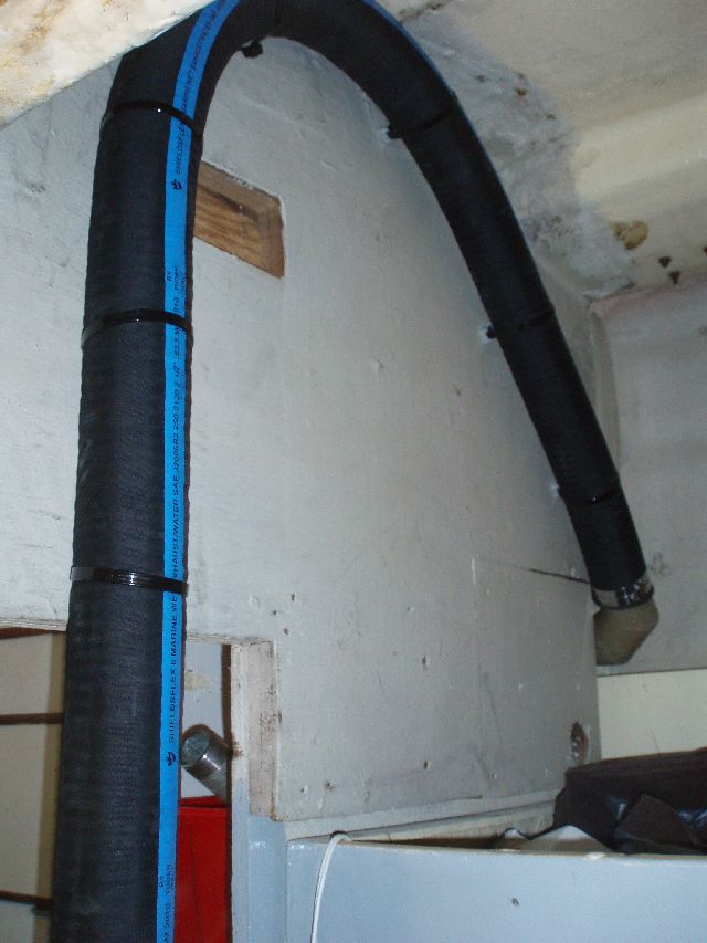
Exhaust hose.


Anti syphon.


Transmission access, not too horrible.


Hose run down port side of hull, to exit at stern. I will secure it in place to give a gentle downward slope.

Monday, June 21, 2010

Engine installation moving along....

Jim E's handiwork again. Everything fits so its off to the welder to be fabricated tomorrow.


Tuesday, June 15, 2010

Engine lift....

One thing I discovered while cruising the Caribbean and Central America is that you can always get stuff fixed in the most unlikely places. However, you need the ability to work on the items in question and sometimes remove them from the vessel using your own resources. I will carry onboard an aluminum "I" beam, a 1 ton chain hoist and a beam trolley to permit to access the transmission and other parts of the engine as necessary. I won't be one bit upset if I never get to use them.


Monday, June 14, 2010

Doctors differ and patients die..........

Well not as dramatic, but lots of conflicting advice on the dry riser. The previous post on the subject quoted the ABYC standard which stated; "No galvanized steel, no brass, no bronze". I have sourced Carbon Steel and this is on standby. Two mechanics, that I have huge respect for, individually suggest galvanized steel and silicon bronze respectively. But I have a cunning plan. I have purchased a second exhaust elbow (hip hip for ebay) and will carry a spare setup.


I am having both elbows cut as indicated above and a 2" threaded galvanized piece welded in place. I can then thread on an 90deg elbow, 18" of pipe, a second 90deg elbow and then the water injecting part of the above. Initially I will use galvanized pipe (cheap and available) but carry the silicon bronze AND the carbon steel as a spare. After a few hundred hours running I will take the riser apart and work from there.

Thursday, May 13, 2010

Engine in....

This is what happens when you leave Jim E. unsupervised.
Things get done.


Final position will be raised approx. 5 ins. Everything else seems to fit.


Front view. H-Beam and chain lift will be setup (put not permanently installed) to allow the engine to be lifted off the mounts and moved aft to permit removal of transmission.

Sunday, April 25, 2010

Correct material for Dry Riser for engine exhaust...

Table 1 in the same Article specifies allowable materials for exhaust systems. The dry exhaust list specifies aluminized steel, carbon steel, nickel-iron chrome and stainless steel. No galvanized steel, no brass, no bronze.

Reference: http://www.ntsb.gov/Dockets/Marine/D...012/234864.pdf

This is the idealised recommendation from the Perkins Sabre installation manual;

"The general arrangement (A) shows that the dry part of the system extends to a safe height above the water line, using an elbow (A1), a stainless steel bellows (A2), a riser pipe to give the required height (A3), and a further elbow (A4), which is supported from the deck head by a flexible hanger, which supports the weight of the system but permits movement side to side and fore and aft."

"The minimum diameter of the dry part of the system should be 40mm (1.6”) for the M65 and the wet part of the system should be not less than 63.5mm (2. 1/2”).

We will see how close we can get. ANY and ALL recommendations and advice graciously accepted.

Fuel fill final....


The upper vent hose goes to a charcoal filter under the teak coaming in the cockpit.

Wednesday, April 21, 2010

Engine exhaust.......

Jim, the guru is trapped in Urop by the evil Icelandic dust so I have time to try and plan the engine exhaust system. From the measurements, I will need a 20"dry insulated riser, with the cooling water injected on the down side.

These are the measurements on TIH.


These are the recommendations from the Vernalift website;


(diagram courtesy of Centek Ind.)

Obviously I have to watch out for excessive back pressure. Any advice welcome.


Wednesday, April 14, 2010

This may have gotten a little out of hand.....

but for what its worth this is the fuel fill system.


All three tanks (Stbd, for'd keel, aft keel) can be filled from one 2" deck fill. The gray elbow at the top is a "Vetus Splash-Stop" device. The days of getting away with fuel squirting out of the boats stern as a means of knowing when to stop pumping is well over. The "Green Marine Fuel Whistle" (white item) gives the first indication and then any overflow goes back into large pipe to the right of the main fill. All tanks can be isolated. I am waiting for 2" fuel hose which is on back order and to connect the 5/8" vent hoses. The vent (brass fitting on the left of the "splash stop" goes to a carbon filter and then to a deck vent.

The black antiphon elbow on the left is for the bilge pump.

Monday, March 29, 2010

ZF25 arrived today....

Caspers little helper arrived today. A ZF25M, possibly the last one available in the US. A new shipment is due in May, but they are hard to find at the moment. When I asked about the 8deg down angle one, everyone just laughed.

Sunday, March 14, 2010

Drivetrain Options......

On my last boat I installed a Vetus Bullflex between the shaft coupling and the transmission. It worked as advertised. However, the $900 price tag seems a bit steep.


Another option that I think is interesting is the "Powertrain Marine Joint".


Friday, March 5, 2010

Transmission decision!!!!!!

For some reason the ZF 25 transmission is on back-order everywhere. Someone is suggesting a Twin-Disc so I am investigating. Any suggestions?

Question for Ocean Dove and any other engineer; Is the 8deg down angle the way to go? I have being trying to work it out but am somewhat confused. Working in metric and imperial measurements is not helping (my guru, Jim is an Imperial guy).

(as a former colleague of mine was fond of saying "four years ago I couldn't spell engenier now I are one").

Monday, February 15, 2010

Behold!!!!, Casper the friendly engine......

hopefully he will never scare anyone (especially me).


A lot of cruisers tend to give names to the individual items on the boat. I won't even try to explain it.

Sunday, February 7, 2010

Houston - we have lift-off


This is the first run of the recently purchased Perkins Sabre M65. The previously mentioned Jim E is the guy you want to have around if you are even marooned on a desert island.

Saturday, January 23, 2010

How much Horse Power do you need in a sailboat?

In the case of a 32ft WLL, 26,000 lbs. sailboat the short answer is 36HP for a nice cruise on Biscayne Bay and 100HP when trying to claw off a lee shore at 3am after you have screwed up your navigation.

Good old Nigel Calder has an excellent table on page 226 of his Marine Diesel Engines (3rd ed). He uses the example of a 32ft WLL, 26,000lb auxiliary sailboat, which is close enough to a fully loaded Whitby 42 to make no difference. Please refer to Calders book for details, but the basic figures are;

Hull speed = 7.58 Kts.
Shaft HP to reach hull speed allowing for 40% prop efficiency = 36.25HP.
Add 33% for power train loss = this gives a BHP of 48HP.

This ties in with all other tables I have seen. Obviously add a few HP for alternators and other bolt on's.

Friday, January 22, 2010

So why can't I install TWO engines.....

in a Whitby 42. I mean if its good enough for Bob Bitchin on his new Shannon 52 RDP?


OK, OK before anyone has a stroke only one of those engines in mine. I hadn't planned on making the engine decision for another year and in the interim I was busy torturing myself with questions about HP, turbo/no turbo, brand etc.

While on a visit to our friends in St. John, Pat and Bev, the Perkins Sabre M65 was mentioned. It pretty well fitted the HP slot between the 80HP recommended by the Whitby purists and the 50/55 HP non-turbo engines that were generally available (see next post on HP requirements). But the engine was out of production.

A few weeks later, when Jim E (previous mentioned boat guru etc.) said that he had a lead on two used Perkins Sabre M65 "at the right price", and would I be interested in one? I was. Pretty much anything that Jim mentions "at the right price', I am interested in, which may result in him being cited in my eventual divorce.

I am now the proud owner on a Perkins Sabre M65 with about 1,800 hrs in need of some cosmetic work, but otherwise in perfect working order.


Wednesday, October 14, 2009

Should I install a diving board?


Probably not, the water in the bilge looks a bit shallow. Still its nice to have access like this to a "real" engine room.

BTW you are looking down through the cockpit sole.